
Em sistemas de radiofrequência ou estações base de comunicação, o Termination Load is a seemingly simple yet critically important passive component. Its role extends beyond merely "absorbing signals" and encompasses system stability, Passive Intermodulation (PIM) control, link testing, and system security. This article will delve into the functions of termination loads within such systems and provide guidance on how to select the right product, alongside three specific product examples.
1. Beyond Termination: Four Pillars of Functionality
A termination load serves a purpose far more critical than simply ending a signal path. Its core functionalities form the foundation of robust and reliable RF system design.
1
)
Eliminating Reflections & Ensuring Signal Integrity
Any unterminated RF port (e.g., an unused power splitter output) becomes a source of signal reflection. This reflected energy degrades the Voltage Standing Wave Ratio (VSWR), causing signal distortion and impairing overall link performance. A termination load provides a perfectly matched impedance, absorbing this disruptive energy to maintain a clean, stable, and efficient transmission line.
2
)
Enabling Precision Testing & Calibration
During system commissioning, maintenance, and optimization, termination loads act as a known, ideal reference. By replacing an antenna or an active component with a load, engineers can simulate a perfect "connected" state. This is essential for accurate power measurement, system gain calibration, and rigorous validation of the link budget—all critical steps for ensuring network performance meets its design specifications.
3
)
Protecting Sensitive Equipment
In laboratory testing or during unexpected operational states, unconnected ports risk exposure to stray or full transmit power. A high-power termination load acts as a reliable protective energy sink, safely dissipating this excess power to prevent damage to sensitive downstream components such as power amplifiers or receivers.
4
)
Suppressing Passive Intermodulation (PIM)
In modern multi-carrier, high-power systems like 5G, passive components can generate nonlinear effects. These effects create harmful intermodulation products that interfere with sensitive receive bands, degrading network capacity. Specifically engineered high-performance, low-PIM termination loads minimize this risk at the source (connection points), thereby preserving signal purity and ensuring overall network performance.
2. Engineered Solutions: Three Loads for Three Challenges
Understanding the application is key to selecting the right tool. Here are three termination loads designed for specific challenges:
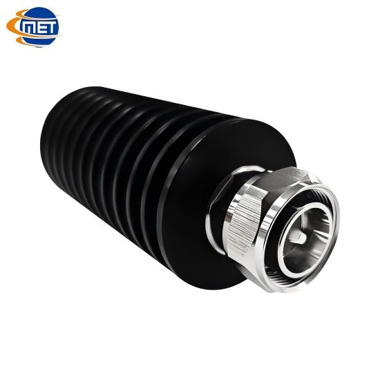
1) DC–6 GHz / 20W Termination Load with 4.3-10 Connector
Wideband Coverage: With a frequency range from DC to 6 GHz, it supports a variety of systems including LTE, 5G, and microwave links.
20W Power Handling: This power rating is well-suited for system debugging, power calibration, and temporary test connections.
Compact 4.3-10 Interface: Its compact and highly compatible design makes it an excellent fit for modern small cell and compact radio unit applications.
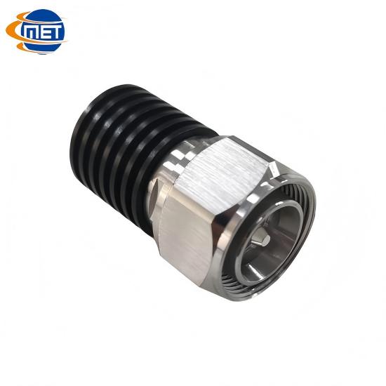
2) DC-3800 MHz / 5W Low VSWR Termination Load with 4.3-10 Connector
High-Band Optimized: Designed for high-frequency applications up to 3.8 GHz, it is ideal for 5G NR deployments and cellular site testing.
Ultra-Low VSWR: Its low Voltage Standing Wave Ratio ensures minimal signal reflection, thereby reducing measurement error and improving test accuracy.
5W Test-Grade Power: Tailored for measurement and calibration tasks, this rating targets precision testing rather than continuous high-power operation.
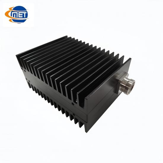
3) 350–1000 MHz / 100W Termination Load with DIN 7/16 Connector
High-Power for Lower Bands: Engineered for the UHF/VHF spectrum (350–1000 MHz) to handle demanding high-power terminations.
100W Power Rating: Capable of withstanding macro-cell level transmit power, making it suitable for public safety systems, private networks, and commissioning of large base stations.
Robust DIN 7/16 Interface: This connector type offers superior power handling and durability, which is ideal for outdoor and high-power environments.
3. Engineering Guidelines: How to Choose the Right Termination Load for Your System
1 ) Identify Your Application Frequency Band
For 5G small cell or micro base station testing, the DC-3800 MHz / 5W model is an excellent fit.
For macro base stations or high-power private network systems, the 350–1000 MHz / 100W model is recommended.
During calibration or benchtop testing phases, the DC–6 GHz / 20W model offers greater frequency flexibility.
2 ) Power Requirement vs. Safety Margin
In system debugging and commissioning, it is advisable to select a load with a power rating slightly higher than the maximum transmit power to prevent overload during the process.
For instance, a 20W load provides a sufficient safety margin for systems tested with transmit power below 10W.
3 ) Connector Type & System Compatibility
The 4.3-10 interface is suitable for modern small cells and compact radio units.
The DIN 7/16 interface is better suited for high-power, outdoor base station environments.
When designing the system topology, ensure the load's connector type matches the cables, couplers, and other components to avoid additional losses from adapters.
4 ) PIM and Linearity Performance
If the system is sensitive to PIM performance (e.g. public safety networks, multi-carrier base stations), selecting a load with excellent PIM characteristics is crucial.
It is recommended to conduct PIM tests (such as measuring intermodulation products under dual-carrier transmission) to verify that the chosen load meets the design specifications.
5 ) Temperature & Environmental Stability
For outdoor or high-temperature environments, the load's material composition and heat dissipation capability are critical factors.
Choosing components that have undergone rigorous reliability testing can prevent performance degradation caused by temperature drift.
4. The Value of Termination Loads in System Operation and Maintenance
1) The Long-Term Stability: High-quality termination loads maintain consistent impedance and reflection characteristics over time, reducing the need for frequent maintenance.
2) PIM Interference Control: Utilizing low-PIM loads helps suppress intermodulation issues that arise when multiple high-power signals coexist.
3) Redundancy for Fault Recovery: Keeping spare loads on hand allows for rapid replacement of faulty links, minimizing network downtime.
4 ) Reference for Debugging: Engineers can use loads as standard impedance references for measuring coefficients, calibrating links, and performing S-parameter tests.
5. Conclusion: A Small Component with a Significant Impact
The Termination Load is not an optional or insignificant component in a system. On the contrary, it plays an irreplaceable role in ensuring signal integrity, managing power, and controlling interference.
During the debugging phase, it serves as an essential calibration tool for engineers.
In normal operation, it acts as a fundamental component that safeguards link stability and minimizes interference.
When selecting a termination load, it is crucial to make a comprehensive judgment based on
frequency band , power requirements , connector type , PIM specifications , environmental conditions .
Based on the three Maniron termination load products discussed above, we recommend:
1) For indoor distribution systems or general testing purposes, the DC–6 GHz / 20W model is the preferred choice.
2) For 5G small cells or test links, the DC-3800 MHz / 5W low VSWR model is worth considering.
3) For macro base stations or public safety systems, the 350–1000 MHz / 100W model provides the necessary high-power assurance.
Choosing the right termination load lays the foundation for network stability and reliability.
Você tem alguma dúvida ?
Ligue-Nos : +86 551 65329702